Simplefied Low-Cost Protection and Control Devices
for Substations and Switchgears 1 - 45
kV
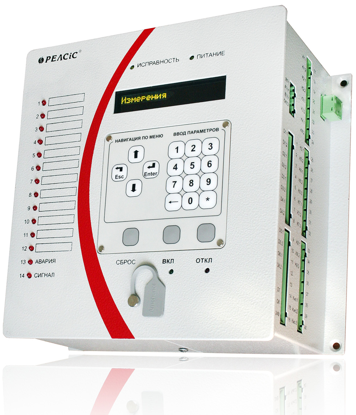
RZL-05.M

A wide range of protection
and automation functions

Combined power supply
including CT circuits unit

Backup trip via CB
current solenoids

Digital oscilloscope
Event log

Integration in
SCADA-system

Environment temperature
-40°C...+60°C

User-defined logics

Fast-operating arc fault
protection with optical fibre
sensor
Application
Microprocessor current protection devices of RZL-05.M series of three-phase execution are suitable for all cases requiring the use of non-directional protection against short circuits between phases, non-directional or directional protection against earth faults and automatic reclosure function.
![]() Download the catalog. Relay Protection and Automation Devices.
Download the catalog. Relay Protection and Automation Devices.
Nomenclature of devices of the RLZ-05.M series:
- RZL-05.M5-B (Y) - device with non-directional OCP and directional EFP, powered by operational
voltage, has backup power supply from current circuits of phases A and C.
RZL-05.M15-B (Y) - additionally has arc fault protection with three optical fibre sensors (OFS). - RZL-05.M6-B (Y) - device with non-directional OCP and directional EFP, powered by operational
voltage, has backup power supply from current circuits of phases A and C, and the function of unloading current
circuits of circuit breaker coils (backup trip via CB current solenoids).
RZL-05.M16-B (Y) - dditionally has arc fault protection with three optical fibre sensors (OFS).
* -B - stand out case, -Y - flush case
Hardware features
- Convenience of mounting according to the type of installation device case (flush or stand-out case).
- Small dimensions (device mounting depth is not more than 10 sm).
- Non-freezing OLED display.
- Number of analog inputs - up to 5 pcs.
- Number of binary inputs - 8 pcs, including 2 inputs «dry» contacts.
- Number of output relays - 9 pcs.
- Number of assigned LEDs - 10 pcs.
- 2 buttons of operational control of the circuit breaker.
- Pluggable terminal blocks with locking latches.
- Current terminals with rated current 63 A, short-term current up to 250 A.
Special characteristics
- High operational features (guaranteed operation in difficult conditions (environment temperature is from -40 to +60 °C, mechanical fulfillment group M7, M43, earthquake resistance).
- Universal device power supply (AC, DC, rectified AC, powered by current circuits).
- USB interface for communication with a PC and two isolated RS-485 for communication with automatic control system (ACS).
- Free programming of discrete inputs, outputs, LEDs.
- Arc fault protection with current control.
- Number of assignable function buttons is up to 10 pcs.
- Two setting groups, control of setting sets for binary inputs or ACS.
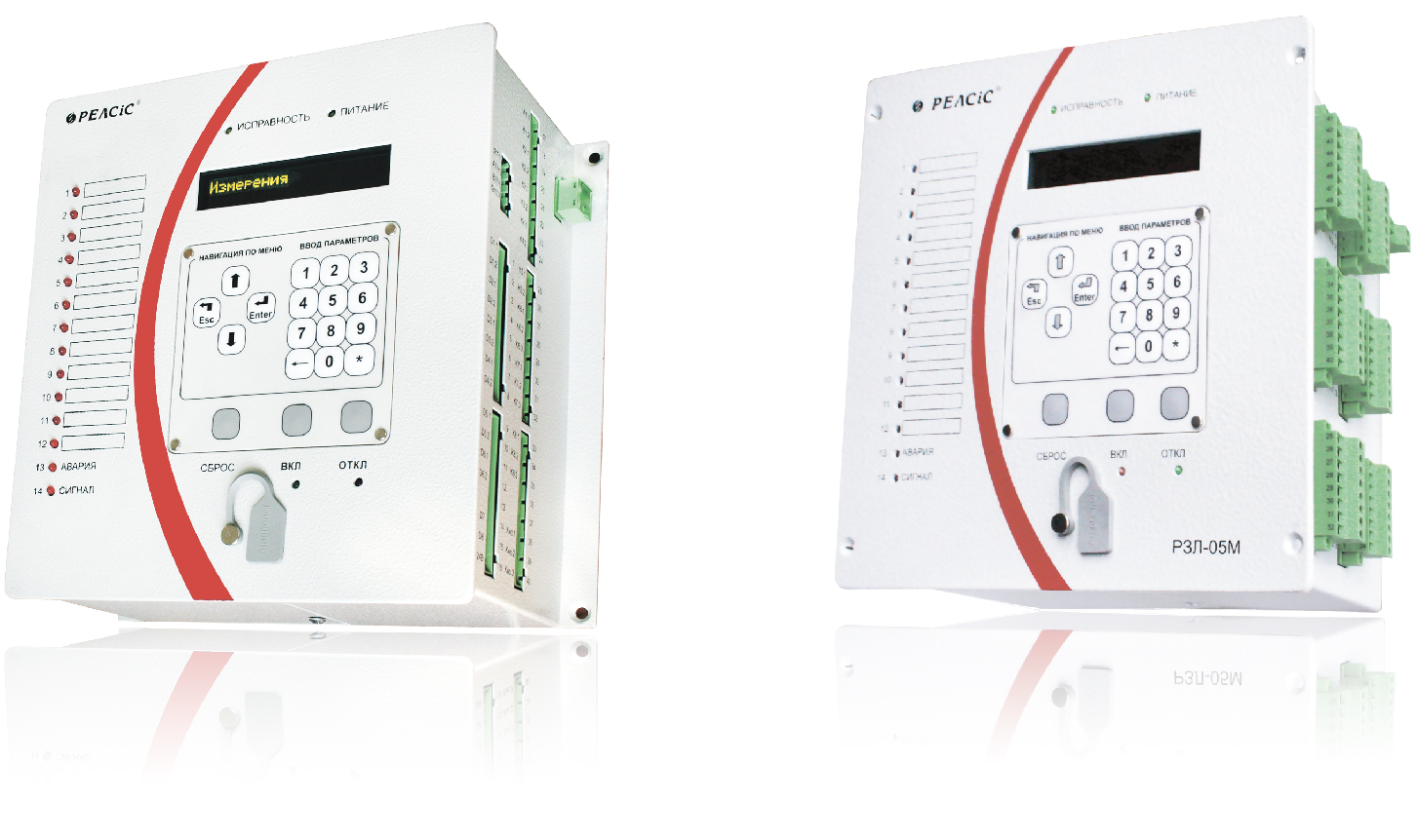
RZL-05.M with flush case and stand out case
Technical parameters
| Power supply units parameters | |
|---|---|
| Operating voltage range, DC or AC | 90 - 254 V |
| Power-on availability time | 0,25 s |
| Operating supply interruption | 0,5 s |
| Independent supply channels (auxiliary voltage circuits) | 1 |
| Device burden | 6 Wt |
| Supply from current transformer circuits (optional) | 2 |
| Continuous current withstand | 2,5 - 10,0 A |
| Current input parameters | |
| Rated input current | 5A |
| Line current inputs number | 3 |
| Measurable current range | 0,3 - 150,0 A |
| Current thermal withstand, 1 s | 10 / 400 A |
| Rated zero-sequence input current (3Io) | 1 A |
| Measurable current 3Io range | 0,01 - 4,00 A |
| Voltage input parameters | |
| Phase voltage | 100 V |
| Number of measured line voltage | 1 |
| Measured voltage range | 1 - 150 V |
| Maximum continuous voltage | 150 V |
| Communication | |
| PC communication interface | RS-485 - 2 pcs |
| Data protocol | Modbus RTU |
| Connection speed via USB, RJ-485 | 9600...38400 bps |
| Binary input parameters | |
| Numbers of inputs | 8 / 6 |
| Rated AC, DC voltage | 230 V |
| Response voltage level | 132 - 176 V |
| Response time | not less 40 ms |
| Current consumption at 220 V: - power-on current - continuous |
20 mA< 4 mA |
| Dry contact binary input parameters | |
| Number of inputs | 2 |
| Dry contact circuits source voltage, DC | 24 V |
| Binary output (relay) parameters | |
| Number of binary outputs / programmable | 8 / 6 |
| AC voltage trip | 400 V |
| Maximum AC current | 8 A (16 A for K1 output) |
| DC voltage trip | 300 V |
| Maximum DC LR-circuit trip current, time constant τ ≤ 20 ms | 0,3 A (0,6 A for K1 output) |
| Outputs for backup trip via CB current solenoids (M3, M6, M13, M16) |
|
| Number of outputs (relays) | 2 |
| Operating range of currents | 1,2 - 150 A |
| Current thermal withstand, 1s | 250 A |
| Other | |
| Mounting type | Flush / stand out |
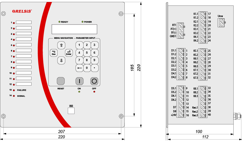
| Device dimensions (WxHxD) | 220x220x112 mm |
| LED indicators total / configurable | 18 / 12 |
| Operating ambient temperature range | -40 to +60 °C |
| Maximum Humidity at 25 °C | 98% |
| Insulation resistance, more than | 50 MΩ |
| Insulation overvoltage withstand, Instantaneous / continuous |
2,0 kV, 50 Hz 5,0 kV pulse |
| Weight, less then | 4,5 kg |
Functions
| Functions | ANSI | M4 | M5 (M15) |
M6 (M16) |
|---|---|---|---|---|
| Backup power supply functions | ||||
| Powered by current circuits (phases of current transformer A and C) | • | • | ||
| Backup trip coils via CB current solenoids | • | |||
| Protection functions | ||||
| Overcurrent protection and current cut-off (OCP + CCO) with time delay (5 stages) | 50/51 | • | • | • |
| Switch on to fault high-speed protection | 50HS | • | • | • |
| Logic Selectivity Busbar protection | 68 | • | • | • |
| Zero-sequence OCP | 50N/51N | • | • | • |
| Directional earth-fault protection | 67N | • | • | |
| Phase conductor break protection (negative sequence or negative to positive sequence ratio current) | 46ВС | • | • | • |
| OCP/zero-sequence OCP stage activation by binary signal (current-restrained intertrip) | • | • | • | |
| Arc-fault protection (by binary input) with phases currents or 3I0 monitoring (3 optical fibre sensors) | 50ARC | (•) | (•) | (•) |
| Automation functions | ||||
| Auto-reclosing | 79 | • | • | • |
| Automatic underfrequency load shedding | 81L | • | • | • |
| HV Breaker failure back-up | 50BF | • | • | • |
| Monitoring and indication functions | ||||
| Breaker closing circuits supervision | 74TCS | • | • | • |
| Protection operation alarm lockout (LED and output state save until manual reset) | • | • | • | |
| Internal malfunction alarm | 30 | • | • | • |
| Parameter setting groups switch on binary input activation/deactivation | • | • | • | |
| Service functions | ||||
| Non-volatile memory event log | • | • | • | |
| Non-volatile memory oscilloscope recorder with 600 s total record duration | • | • | • | |
| Oscilloscope on binary input activation | • | • | • | |
Dimensions
Wiring Diagrams
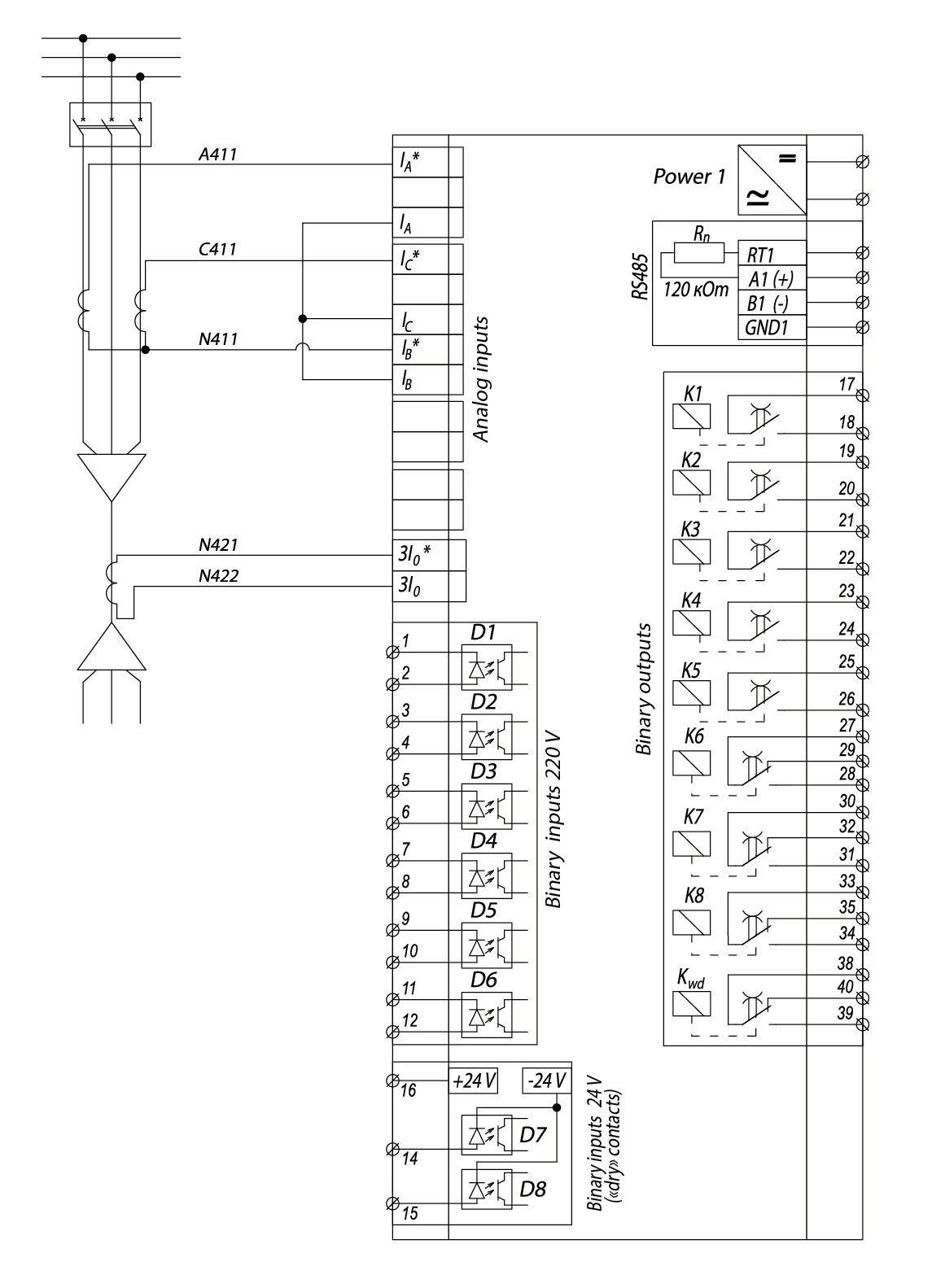
Wiring diagram of external circuits to the devices RZL-05.M1
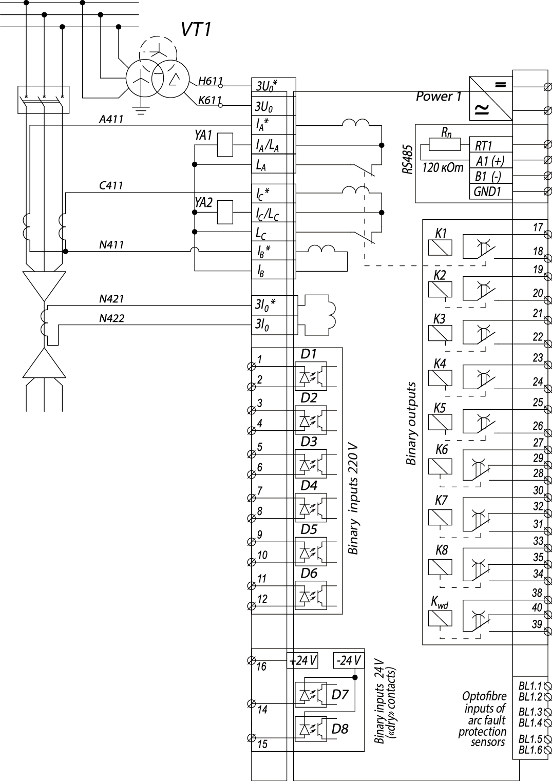
Wiring diagram of external circuits to the devices RZL-05.M16
![]() Download the catalog. Relay Protection and Automation Devices.
Download the catalog. Relay Protection and Automation Devices.
