Transformer Differential Protection
RZL-05.T2, RZL-05.T3

RZL-05.T

A wide range of protection
and automation functions

Digital oscilloscope
Event log

Integration in
SCADA-system

Environment temperature
-40°C...+55°C

User-defined logics

Fast-operating arc fault
protection with lens-type
photosensor
Application
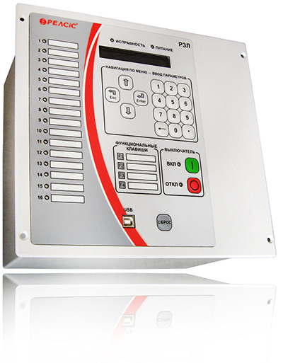
Microprocessor devices of RZL-05.T series are intended to perform differential protection of two-winding and three-winding power transformers with 35 - 110 kV HV winding. Devices are to be mounted in relay sections of switchgears and also relay panels and substation control boards.
![]() Download the catalog. Relay Protection and Automation Devices.
Download the catalog. Relay Protection and Automation Devices.
Features
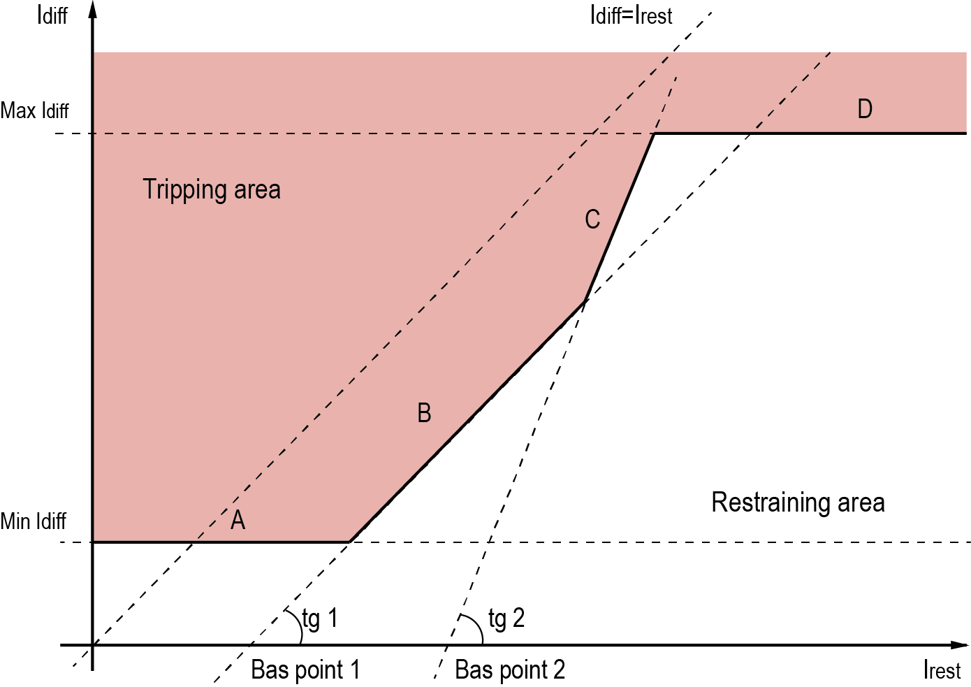
- Two differential protection zones: differential current cutoff without restraining and sensitive differential current protection restrained in case of external fault out of protection area and from magnetising inrush current.
- Current circuits performance supervision production blocking in case of loss.
- Five-stage overcurrent protection including current cutoff with magnetizing current inrush restriction, current overload protection with the definite and independent time-delay. For overcurrent protection stages available an option of voltage controlled start.
- Logical selectivity busbar protection.
- Three-stage ground fault protection of HV winding. Zero-sequence fault current may be measured or calculated.
- Phase loss protection (negative-sequence) current protection.
- Logics of internal transformers protection performance. Each internal protection command might be configured to trip or to initiate an emergency alarm.
- Light-sensor arc fault protection.
- Breaker failure protection.
- User-defined programmable logic.
- Solid ambient conditions withstand (-40...+55 °C).
- Multi-lingual LCD interface: English, Ukrainian, Russian.

Restraining curve of differential protection
Technical parameters
| Parameters | RZL-05.T2 - | RZL-05.T3 - | ||
|---|---|---|---|---|
| 1 | 5 | 1 | 5 | |
| Power supply units parameters | ||||
| Operating voltage range, DC / AC, 50 Hz | 90 – 360 V / 80 – 254 V | |||
| Power-on availability time | 0,3 s | |||
| Operating supply interruption | 0,5 s | |||
| Independent supply channels (auxiliary voltage circuits) | 2 | |||
| Device burden | 2x13 Wt | |||
| Current input parameters | ||||
| Rated input current | 5 A | |||
| Line current inputs number | 6 | 9 | ||
| Measurable current range | 0,3 - 125,0 A | |||
| Maximum monitored current value | 150 A | |||
| Basic relative measurement accuracy | ±2 % | |||
| Current thermal withstand, continuous / 1 s | 10 / 500 A | |||
| Zero-sequence current input parameters | ||||
| Rated zero-sequence input current (3Io) | 1 A | 5 A | 1 A | 5 A |
| Line current inputs number | 1 | |||
| Measurable current range | 0,01 - 2 A | 0,5 - 125 A | 0,01 - 2 A | 0,5 - 125 A |
| Maximum monitored current value | 10 A | 150 A | 10 A | 150 A |
| Current thermal withstand, continuous / 1 s | 5 / 100 A | 15 / 500 A | 5 / 100 A | 15 / 500 A |
| Voltage input parameters | ||||
| Phase voltage | 100 V | |||
| Number of inputs | 4 | |||
| Rated voltage range | 1 - 150 V | |||
| Maximum controlled voltage | 200 V | |||
| Linear voltages measurement accuracy | ±2 % | |||
| 3Uo voltage measurement accuracy | ±3 % | |||
| Voltage thermal withstand, continuous /1 s | 150 / 300 V | |||
| Measurement accuracy of phase angles between current 3Іо and voltage 3Uо | ±3 deg | |||
| Thermal sensor input parameters | ||||
| Number of inputs | 1 | |||
| Temperature range | 0- 100 °C | |||
| Binary input parameters | ||||
| Number of inputs | 9 | 17 | ||
| Rated AC, DC voltage | 220 V | |||
| Response voltage level | 132 - 176 V | |||
| Response time | not less 40 ms | |||
| Current consumption at 220 V:
- power-on current - continuous |
20 mA 4 mA |
|||
| Maximum voltage, continuous | 310 V | |||
| Dry contact binary input parameters | ||||
| Number of inputs | 13 | 17 | ||
| Dry contact circuits source voltage | DC 24 V | |||
| Binary output parameters | ||||
| Number of binary outputs | 13 | 17 | ||
| Max AC voltage trip | 400 V | |||
| Maximum AC current | 5 A (10 A for K1 output) | |||
| Max DC voltage trip | 300 V | |||
| Maximum DC LR-circuit trip current, time constant τ≤20 ms | 0,2 A (0,4 A for K1 output) | |||
| Arc fault protection sensors parameters | ||||
| Number of inputs | 3 | |||
| Response threshold | 900 – 1700 lux | |||
| Communication | ||||
| PC communication interface | USB - 1 pcs | |||
| Automated Control System communication interface | RS-485 - 2 pcs | |||
| Data Protocol | MODBUS RTU | |||
| Connection speed | 9600...115200 bps | |||
| Other | ||||
| Mounting type | Flush | |||
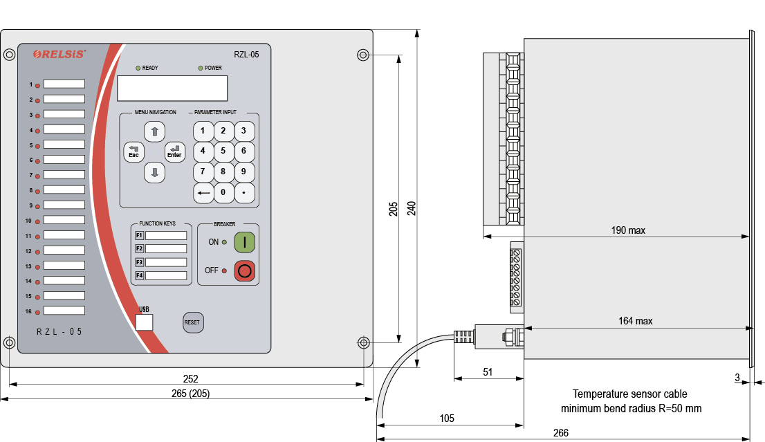
| Device dimensions (WxHxD) | 205x240x195 mm | 265x240x195 mm | ||
| Weight, less then | 6,5 kg | 10 kg | ||
| LED indicators total / configurable | 20 / 16 | |||
| Operating ambient temperature range | - 40 to + 55 °C | |||
| Maximum Humidity at 25 °C | 98 % | |||
| Insulation resistance, more than | 50 MΩ | |||
| Insulation overvoltage withstand, Instantaneous / continuous |
2,0 kV , 50 Hz 5,0 kV pulse |
|||
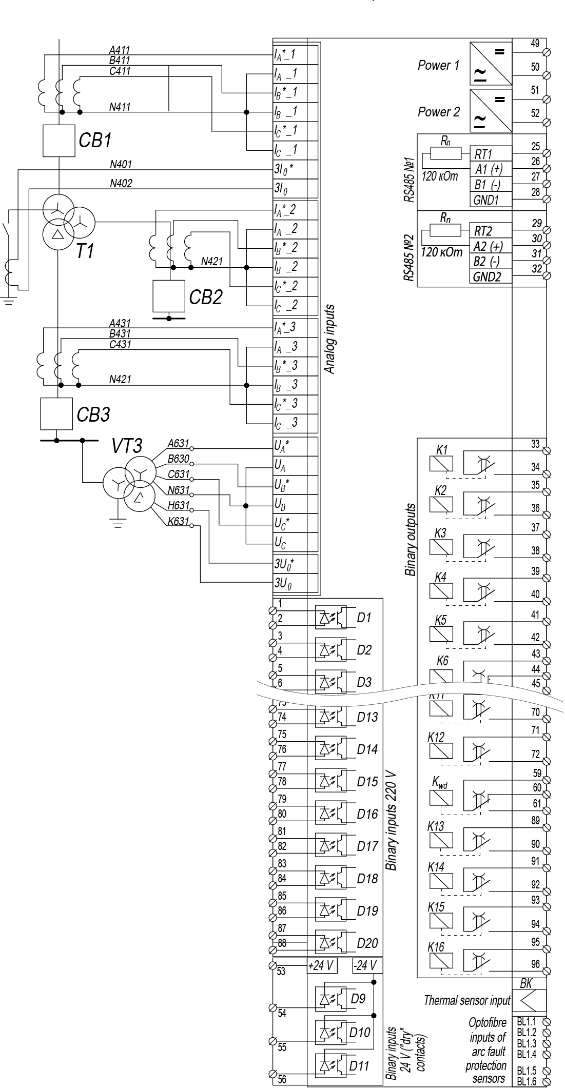
Wiring Diagram example

Wiring diagram of external circuits to the devices RZL-05.T3-5
Dimensions

![]() Download the catalog. Relay Protection and Automation Devices.
Download the catalog. Relay Protection and Automation Devices.
