Relay Protection Devices for 6 - 35 kV Distribution Networks
RZL-01

Redundant CT circuits
bypass power source
Backup trip via CB
current solenoids
Digital oscilloscope
Event log

Integration in
SCADA-system
Application
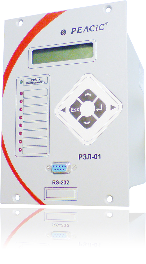
The microprocessor relay protection device RZL-01 is designed to perform the functions of relay protection, automation, control, registration and alarms of:
- cable and overhead 6-35 kV lines;
- backup power transformer protection and others.
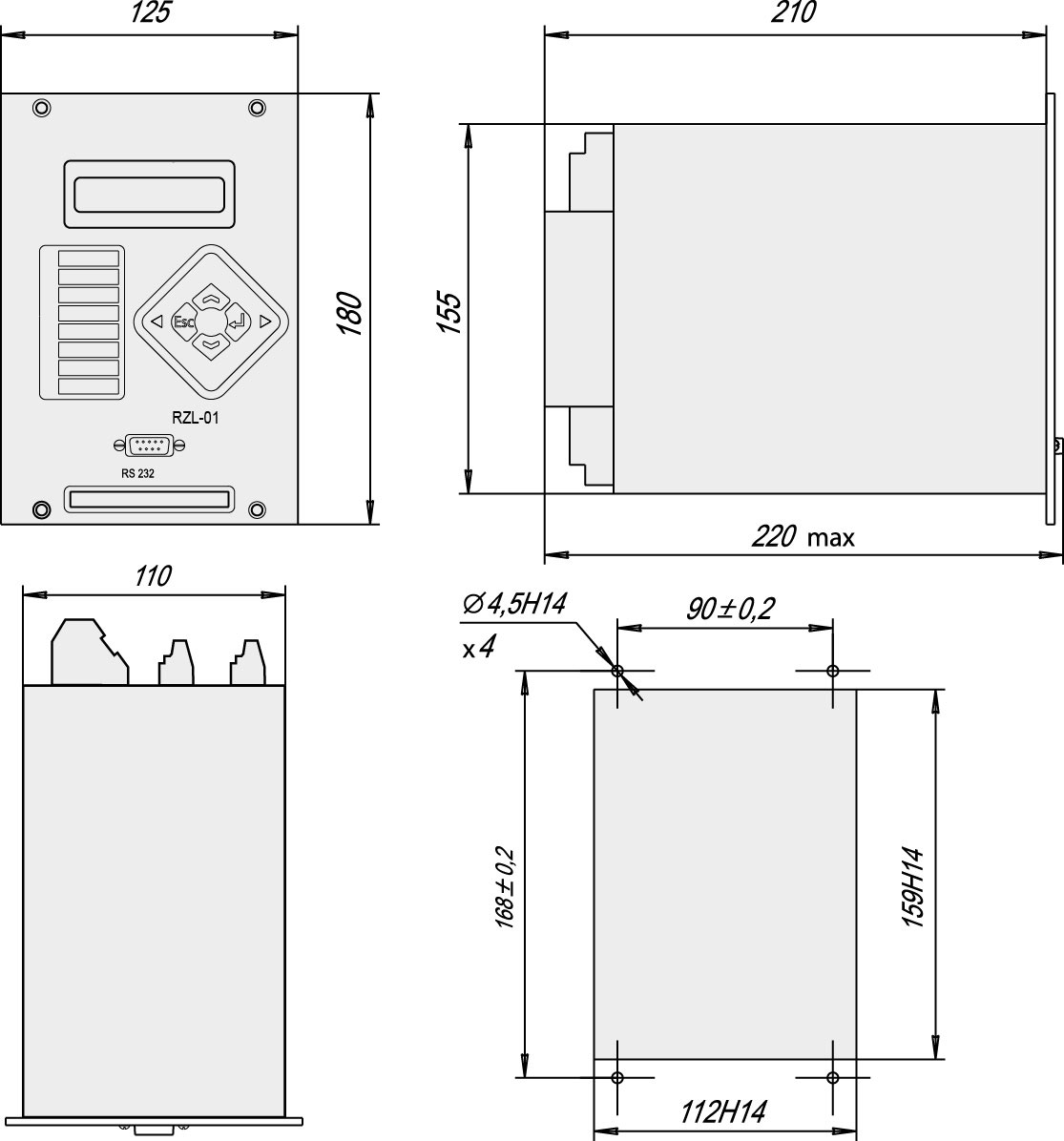
The device is designed for installation in relay sections and compartments of switchgears, in control panels and boxes located in the relay halls and on the control desks of power substations 6-35 kV.
The device can be used for protection of distribution networks elements as an independent device, and in combination with other devices of relay protection and control systems.
![]() Download the catalog. Relay Protection and Automation Devices.
Download the catalog. Relay Protection and Automation Devices.
Features
- Performance of protection functions, automatics and control, complies with regulations requirements
- User-defined variable internal configuration (binary inputs, outputs and LEDs)
- Configuration setting via human-machine interface and/or software tool included
- Entering and saving settings of protection and relay control devices
- Free assignment of LED indicators for displaying status of binary inputs, starts/operation of the overcurrent protection / ground fault protection (OCP/GFP), re-closure failure, OCP acceleration, and other service functions
- One current-time responsible OCP stage
- Configurable binary outputs for protection start/operation functions of OCP/GFP, automatic reclosing, circuit breaker failure backup, busbar lockout protection
- Free configurable 16 channels of event logging (logic functions and binary input/output state)
- Remote control, measuring, alarm signalization, entry and change of settings via communication lines
- Self-supervision (watchdog) and self-blocking on failure
- Opto-coupler binary inputs insulation
Protection functions
- Each OCP stage acceleration on CB closing operations
- Single-stage non-concentrated GFP protection
- Busbar instantaneous protection lockout
- Interconnecting of external protection
Automation function
- CB operation on external commands
- Single/double automatic re-closing after OCP/GFP operation, external protection command on binary input (IN). Reclosing operation on the certain OCP stages
- CBFP on designated overcurrent stages by "Working GFP" signal, by external signal from designated binary input (IN)
Additional service functions
- Built-in clock and calendar
- Measurement of phase currents and zero sequence current 3I0, and their primary/secondary value display
- Digital fault recorder with non-volatile memory
- Event log
- Statistics register
- Multi-lingual LCD interface: English, Ukrainian, Russian
Technical parameters
| Rated input signals, auxiliary power supply | |
| Rated input phases current In / zero-sequence current 3I0 In3I0 | 5 A or 1 A / 1 A |
| Voltage range (DC or AC) | 90-250 V AC/DC, 45-55 Hz |
| Powerconsumption + per each binary output energized | 5 V·A + 0,4 V·A |
| Instantaneous current inrush on energize (10 μs) | 10 A |
| Operating supply interrupt duration | 500 ms |
| Self-test availability time: - Auxiliary voltage supply
- Current circuits supply |
50 ms 150 ms |
| Self-test duration | 250 ms |
| Backup supply from current circuits (RZL-01.02, RZL-01.03) | |
| Minimum / Rated / Continuous current | 4 A / 5A / 20 A (4 In) |
| Voltage input power | 2,5 V·A |
| Maximum analog input power | 12 V·A |
| Three-stage overcurrent protection /OCP/ | |
| Current setting range | 0,1 — 25 In, step 0,1 A |
| OCP time-delay instance setting range | 0 — 32 s, step 0,05 s |
| OCP acceleration instance setting range / OCP setting time | 0 — 5 s / 0 — 5 s, step 0,1 s |
| Non-directional ground-fault protection /GFP/ | |
| Current instance setting range | 0,01 - 1 A, step 0,01 A |
| Time-delay setting range | 0 — 32 s, step 0,05 s |
| Auto-reclosing /AR/ | |
| 1st and 2nd ARC cycles time-delay setting range | 0,8 — 600,0 s, step 0,1 s |
| Next ARC cycle availability time range | 0,9 — 600,0 s, step 0,1 s |
| AR preparation time | 30 — 600,0 s, step 0,1 s |
| Breaker failure back-up | |
| Current instance setting range | 0,1 — 25 In, step 0,1 A |
| Time-delay setting range | 0,1 — 4,0 s, step 0,1 s |
| Binary inputs | |
| RZL-01.01, RZL-01.02, RZL-01.03 voltage activation binary inputs with opto-coupler insulation |
6 |
| RZL-01.02 D2, RZL-01.03 D2 voltage activation binary inputs with opto-coupler insulation dry contact binary inputs (galvanically connected with power supply circuits) |
4 2 (inputs D5, D6) |
| RZL-01.02 D3, RZL-01.03 D3 voltage activation binary inputs with opto-coupler insulation dry contact binary inputs (galvanically connected with power supply circuits) |
3 3 (inputs D4, D5, D6) |
| RZL-01.02K1 voltage activation binary inputs with opto-coupler insulation |
5 |
| Input-to-output command transfer time-delay setting range (for each input) | 0 — 32,0 s |
| Control voltage DC Un | 220 V (110 V*)
U«1» > 0,6Un; U«0» < 0,4Un |
| Control voltage AC 50 Hz Un | 220 V (110 V*)
U«1» > 0,8Un; U«0» < 0,45Un |
| Dry contact inputs internal supply module voltage | 310 V (154 V*) DC ** |
| Operation threshold deviation | ±0,1·Un |
| Input resistance | 50 kOhm |
| Binary outputs | |
| Number of programmable outputs - NO+NC contact / - NO contact | 1 / 4 (1 / 3 - in RZL-01.02K1) |
| Internal fail signal output, switch contact | 1 |
| Switching ability of relay contacts
- Maximum tripping AC voltage / current / power (cosφ=0,6) - Maximum turn-on DC voltage / current / (τ=30 ms) - Maximum DC tripping power - Rated continuous AC/DC current |
220 V, 5 A, 1000 VA (cosφ=0,6) 250 V / 0,4 A 30 Wt 8 A |
| Insulation parameters | |
| Current inputs insulation to coating and voltage inputs between inputs and input to the ground | AC 2000 V, 50 Hz, 1 min |
| The rest, galvanically isolated. circuits (except for the closing of the relay contacts) | AC 1500 V, 50 Hz, 1 min |
| Outputs of NO contacts of electromagnetic relays | AC 500 V, 50 Hz, 1 min |
| Short-time thermal resistance of current circuits | |
| RZL-01.01: during 1 sec / 60 sec | 80·In / 8·In |
| RZL-01.02 and RZL-01.03: during 1 sec / 60 sec | 50·In / 4·In |
| Device surge, static electicity, disturbance withstand performed by GOST 29280 (EN61000-4-2 - EN61000-4-11) | |
| Analog inputs withstand: - voltage surges (three positive, three negative) | 5kV, 1,2/50 μs, 3 "+", 3 "-" |
| - high frequency disturbance (maximum instantaneous vakue): longitude / transverse | 2,5 kV / 1,0 kV |
| - operating supply interrupt duration | 500 ms |
| Operating ambient temperature range
Storage and transportation |
UHL4: -20°C ... +55°C,
UHL3.1: -40°C ... +70°C |
| Communication | |
| Protocol | Modbus RTU |
| Interfaces / Connection speed | RS485 / 9600 / 19200 / 38400 bps
RS232 / 19200 bps |
** Binary inputs D4, D5, D6 for modifications RZL-01.xx D2/D3 are supplied from an internal power module and their terminals are galvanically connected with power supply terminals.
Wiring Diagrams
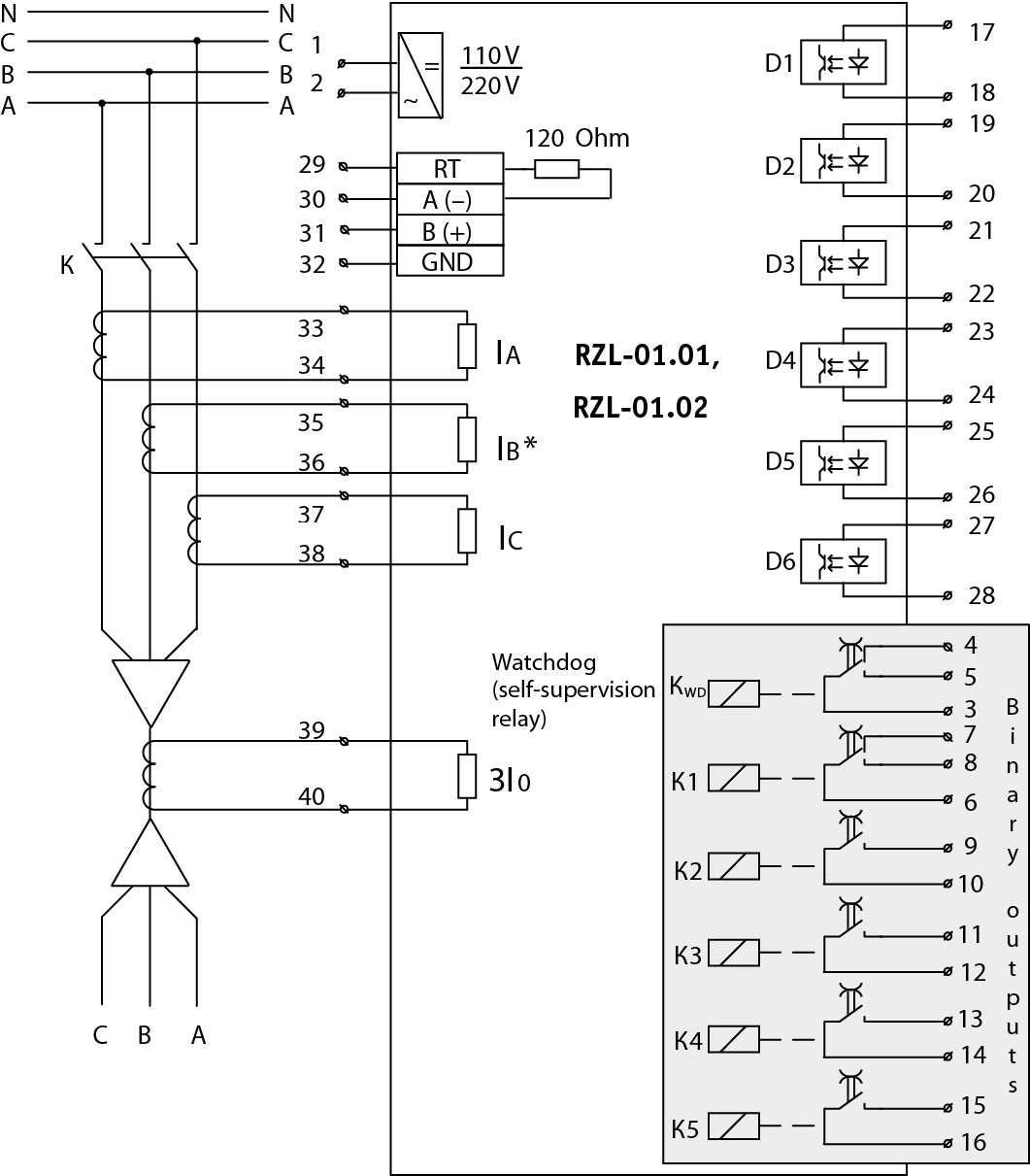
Wiring diagram of external circuits to the devices RZL-01.01, RZL-01.02
1. The RT, A, B, GND inputs are used to connect the RS485 bus (RT-B - connect the jumper to enable the internal 120-ohm terminating resistor).
2. The states of all relays shown in "off" position. Self-supervision relay KWD closes the contacts 3-5 after powering (if relay malfunction - closes contacts 3-4).
3. Binary inputs D1-D6 are independent of connection polarity.
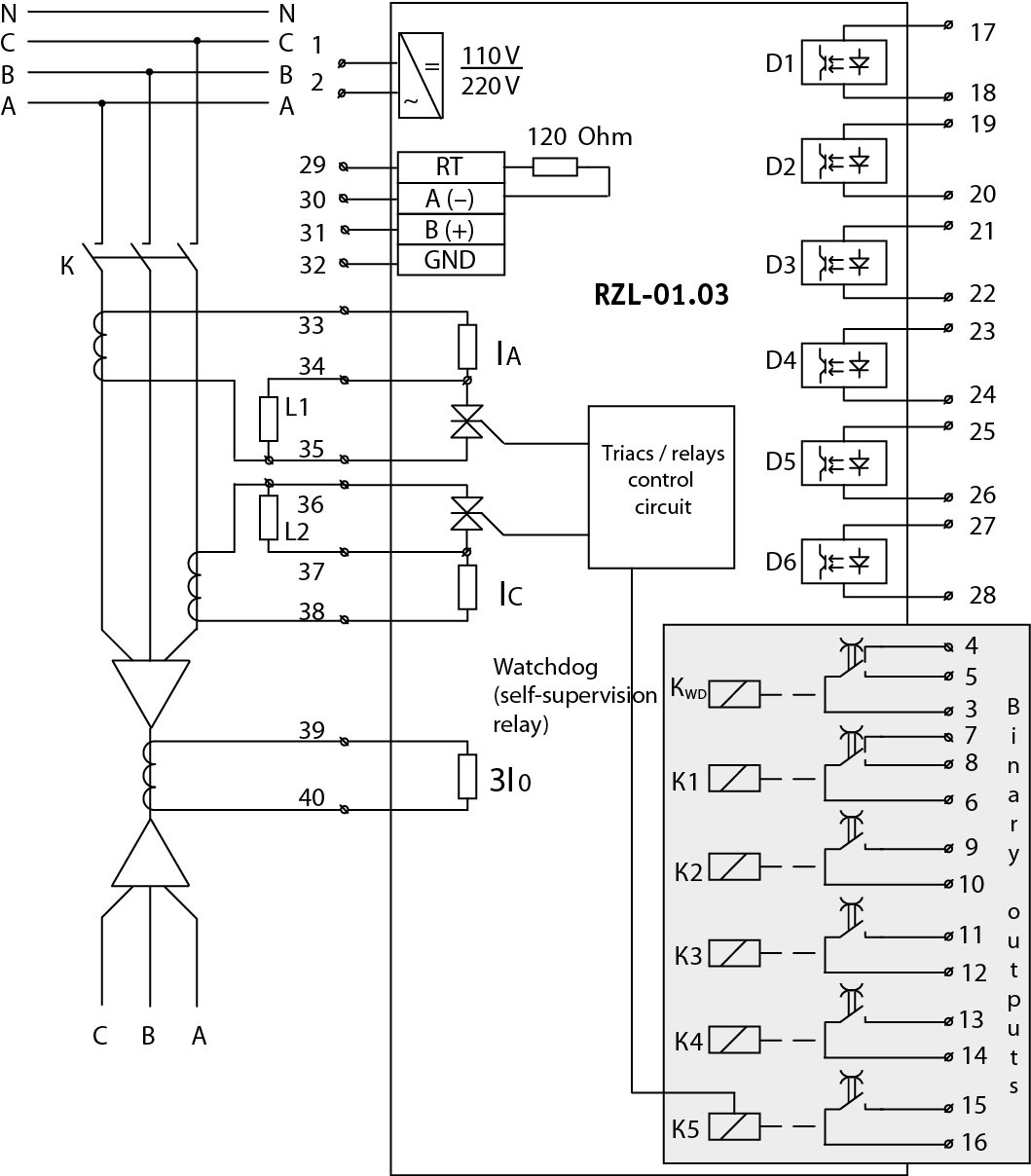
Wiring diagram of external circuits to the device RZL-01.03
with backup trip current solenoids circuit L1, L2 - trip-coils of breaker solenoids.
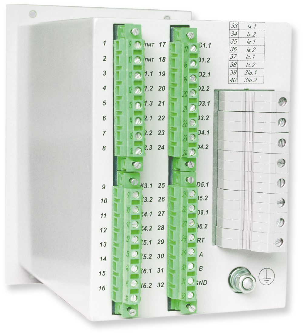
Dimensions
![]() Download the catalog. Relay Protection and Automation Devices.
Download the catalog. Relay Protection and Automation Devices.
