Advanced Protection and Control Devices
for Substations and Switchgears 1 - 45 kV
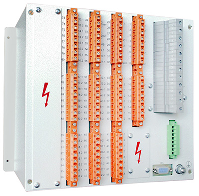
RZL-05.A
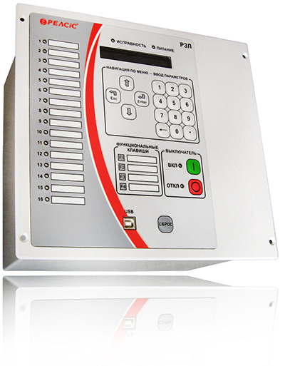

A wide range of protection
and automation functions

Combined power supply
including CT circuits unit

Backup trip via CB
current solenoids

Digital oscilloscope
Event log

Integration in
SCADA-system

Environment temperature
-40°C...+60°C

User-defined logics inclusion
available (on demand)

Fast-operating arc fault
protection with lens-type
photosensor
Application
New modified electronic microprocessor devices series RZL-05 are used for protection, automation, control and monitoring of power distribution network elements. Devices are the most suitable for incoming / outgoing feeder (RZL-05.Ax B) and busbar section coupler (RZL-05.Ax BS) bays of 1 - 45 kV distribution networks.
Devices can be installed in relay cubicles of switchgear bays.
![]() Download the catalog. Relay Protection and Automation Devices.
Download the catalog. Relay Protection and Automation Devices.
Features
- Protection, automation and control of an intended network elements;
- Operating parameters settings via built-in HMI and PC software tool: functions activation/deactivation, protection stages values and time delay for each stage etc.;
- Three photosensor inputs of arc-fault protection;
- Each photosensor input independent configuration;
- Fault recorder and event log;
- Total fault record duration over 600 s;
- A solid number of inputs, outputs and indicating LEDs;
- Flexible configuration settings;
- Non-volatile storage of setting, events, fault recordings;
- Data transfer including current parameter and function settings, apparatus state, events, measurements;;
- Remote control functions;
- Wire connection terminals with end-position locking plug;
- Steel casing;
- Front side USB interface;;
- Two RS-485 interfaces of MODBUS data transfer protocol;
- Real-time self-supervision;
- Self-blocking on internal failure to prevent false operations;
- Two mutually redundant power supply units;
- Optional current circuits low-burden redundant power supply;
- AC/DC power supply source;
- Binary inputs optocoupler isolations;
- Supply inputs and all signal circuits are galvanically isolated;
- Solid overvoltage withstand;
- Solid ambient conditions withstand;
Technical parameters
| Power supply units parameters | |
| Operating voltage range, DC or AC | 90 - 254 V |
| Power-on availability time | 0,19 s |
| Operating supply interruption | 0,5 s |
| Independent supply channels (auxiliary voltage circuits) | 2 |
| Device burden | 10 Wt |
| Supply from current transformer circuits (optional) | 2 |
| Continuous current withstand | 2,5 - 20,0 A |
| Current input parameters | |
| Rated input current | 5A |
| Line current inputs number | 3 |
| Measurable current range | 0,3 - 200,0 A |
| Current thermal withstand, 1 s | 10 (500) A |
| Rated zero-sequence input current (3Io) | 1 A |
| Measurable current 3Io range | 0,01 - 4,00 A |
| Voltage input parameters | |
| Phase voltage | 100 V |
| Number of inputs | 3 |
| Rated voltage range | 1 - 150 V |
| Maximum continuous voltage | 130 V |
| Thermal sensor input parameters | |
| Number of inputs | 1 |
| Temperature range | 0 - 125 °C |
| Communication | |
| USB interface | 1 |
| RS485 interface | 2 |
| Data protocol | Modbus RTU |
| Connection speed | 9600, 19200, 38400 kbps |
| Binary input parameters | |
| Numbers of inputs | 17 |
| Rated AC, DC voltage | 230 V |
| Response voltage level | 132 - 176 V |
| Response time | 40 ms |
| Current consumption at 220 V: - power-on current - continuous |
20 mA< 4 mA |
| Maximum voltage, continuous | 310 V |
| Dry contact binary input parameters | |
| Number of inputs | 3 |
| Dry contact circuits source voltage, DC | 24 V |
| Binary output parameters | |
| Number of binary outputs | 17 |
| Maximum DC voltage trip | 300 V |
| Maximum AC voltage trip | 400 V |
| Maximum AC current | 8 A (16 A for K1 output) |
| Maximum DC LR-circuit trip current, time constant τ ≤ 20 ms | 0,3 A (0,6 A for K1 output) |
| Other | |
| Mounting type | Flush |
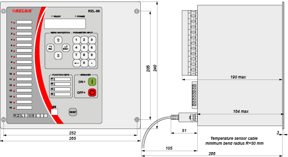
| Device dimensions (WxHxD) | 265x240x190 mm |
| LED indicators total / configurable | 20/8 |
| Operating ambient temperature range | -40 to +55 °C |
| Maximum Humidity at 25 °C | 98% |
| Insulation resistance, more than | 50 MΩ |
| Insulation overvoltage withstand, Instantaneous / continuous |
5 / 2 kV |
| Weight, less then | 10 kg |
Function
| Function | ANSI | RZL-05.Ax B | RZL-05.Ax BS | ||||||
|---|---|---|---|---|---|---|---|---|---|
| Protection | 1 | 2 | 3 | 4 | 1 | 2 | 3 | 4 | |
| Overcurrent (OCP) | 50/51 | • | • | • | • | • | • | • | • |
| Voltage-restrained OCP | 50V/51V | • | • | • | • | • | • | • | • |
| OCP stage blocking by binary input | • | • | • | • | • | • | • | • | |
| Directional OCP | 67 | • | • | • | • | • | • | • | • |
| Negative-sequence overcurrent | 46 | • | • | • | • | • | • | • | • |
| Switch on to fault high-speed protection | 50HS | • | • | • | • | • | • | • | • |
| Logic Selectivity Busbar protection | 68 | • | • | • | • | • | • | • | • |
| Zero-sequence OCP (unidirectional ground-fault protection) | 50N/51N | • | • | • | • | ||||
| Directional ground-fault protection (directional zero-sequence power protection) | 67N | • | • | • | • | ||||
| Zero-sequence overvoltage protection | 59N | • | • | • | • | • | • | • | • |
| Overvoltage protection | 59 | • | • | • | • | • | • | • | • |
| Undervoltage protection with a current-permissive instance | 27 | • | • | • | • | • | • | • | • |
| Negative-sequence overvoltage protection | 47 | • | • | • | • | • | • | • | • |
| Phase conductor break protection (negative sequence or negative to positive sequence ratio cirrent) | 46BC | • | • | • | • | • | • | • | • |
| OCP/zero-sequence OCP stage activation by binary signal (current-restrained intertrip) | • | • | • | • | • | • | • | • | |
| ARC-fault protection (3 optofibre sensor inputs) | • | • | • | • | |||||
| Overtemperature protection | • | • | • | • | • | • | • | • | |
| Automation functions | |||||||||
| Auto-reclosing | 79 | • | • | • | • | ||||
| Automatic underfrequency load shedding | 81L | • | • | • | • | ||||
| HV Breaker failure back-up | 50BF | • | • | • | • | • | • | • | • |
| Automatic load transfer | • | • | • | • | • | • | • | • | |
| Automatic initial scheme restore | • | • | • | • | • | • | • | • | |
| Monitoring and indication functions | |||||||||
| Breaker closing circuits supervision | 74TCS | • | • | • | • | • | • | • | • |
| Temperature monitoring via thermal sensor | 38/49T | • | • | • | • | • | • | • | • |
| Protection operation alarm lockout (LED and output state save until manual reset) | • | • | • | • | • | • | • | • | |
| Internal malfunction alarm | 30 | • | • | • | • | • | • | • | • |
| Voltage transformer secondary circuits supervision | • | • | • | • | • | • | • | • | |
| Parameter setting groups switch on binary input activation/deactivation | • | • | • | • | • | • | • | • | |
| Service functions | |||||||||
| Non-volatile memory event log | • | • | • | • | • | • | • | • | |
| Non-volatile memory fault recorder with 600 s total record duration | • | • | • | • | • | • | • | • | |
| Fault recorder on binary input activation | • | • | • | • | • | • | • | • | |
Wiring Diagrams
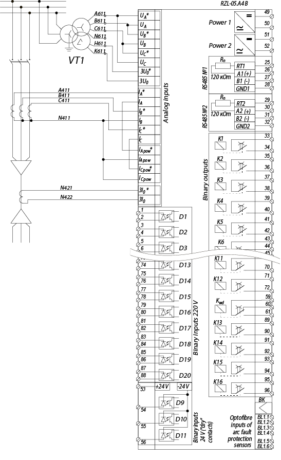
Wiring diagram of external circuits to the devices RZL-05.A4 B
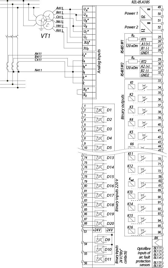
Wiring diagram of external circuits to the devices RZL-05.A3 BS
Dimensions
![]() Download the catalog. Relay Protection and Automation Devices.
Download the catalog. Relay Protection and Automation Devices.
