Protection and Control Devices
for Protection and Control of Voltage Transformer
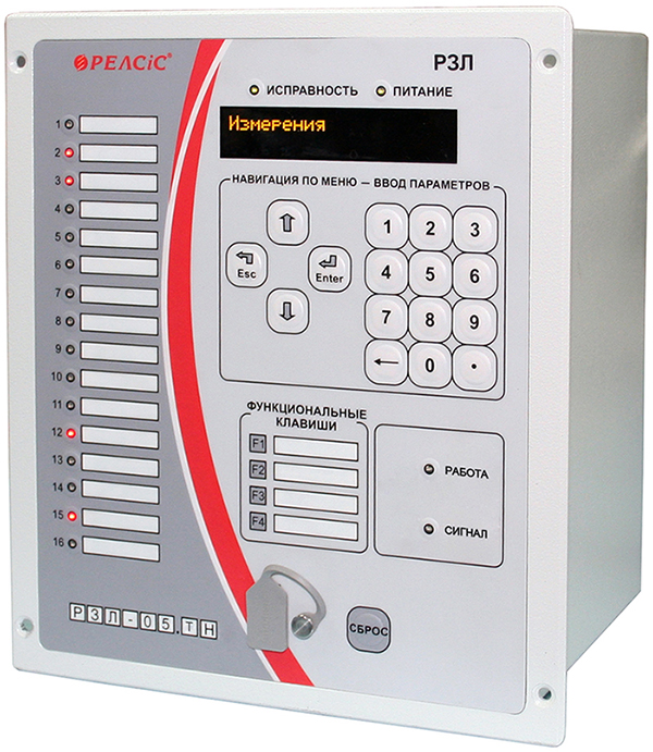
RZL-05.VT


Digital oscilloscope
Event log

Integration in
SCADA-system

Environment temperature
-40°C...+55°C

User-defined logics
Application
Microprocessor devices RZL-05.VT are used for relay protection, automation, control, registration and alarm signaling of voltage transformers 110–35–10(6) kV of complete switchgears at power and industrial facilities.
Devices are designed for facilities: distribution networks, transformer substations, stations with guaranteed (AC, DC or rectified voltage) and non-guaranteed operational current.
Devices are to be mounted into relay cubicles of switchgears, relay panels.
Devices have user-defined logics inclusion.
![]() Download the catalog. Relay Protection and Automation Devices.
Download the catalog. Relay Protection and Automation Devices.
Features
- Complex substation protection by voltage (monitoring and control of voltage transformer VT1 of the first busbar section, VT2 - auxiliary transformer).
- Operating parameters settings via built-in HMI and PC software tool: functions activation/deactivation, protection stages values and time delay for each stage e t.c.
- Individual configuration of each photosensor input.
- Flexible configuration settings.
- Non-volatile storage of settings, events, fault recordings.
- Total waveform recording duration 600 s.
- A solid number of output relays, incl. one reinforced relay for switching high values instantaneous currents, switching in circuits with high inductance, and one bistable relay, eliminating the need to install additional relays.
- Remote configuration and data transfer including current parameters and function settings, apparatus state, events, measurements via RS-485 interface by MODBUS RTU protocol.
- Remote control of HV devices via MODBUS RTU protocol.
- Steel casing.
- Front side USB interface.
- Real-time self-supervision.
- Two switchable setting groups.
- Two mutually redundant power supply units.
- Universal AC/DC power supply source.
- Supply input and all signal circuits are galvanically isolated.
- Solid overvoltage withstand.
- Optocoupler-insulated binary inputs.
- Interredundant hardware and software to improve the reliability of protection, automation functions and data transfering.
- Presence of digital inputs, controlled by "dry contact", and which saves execution of their functions when switching-off operational power supply.
- Solid ambient conditions withstand (-40...+55 °C).
- Multi-lingual LCD interface: English, Ukrainian, Russian.
Functions
| Protection functions | ANSI |
|---|---|
| Voltage-restrained OCP | 50V/51V |
| Zero-sequence overvoltage protection (3 stages) | 59N |
| Overvoltage protection (2 stages) | 59 |
| Undervoltage protection (3 stages) | 27 |
| Auxiliary channel overvoltage protection | |
| Reverse sequence overfrequency protection | |
| External protection by binary input | |
| Arc fault protection by binary input | |
| Overfrequency protection | |
| Device overheat protection | |
| Parameter setting groups switch by binary input activation/deactivation | |
| Automation functions | |
| Automatic underfrequency load shedding | 81L |
| Monitoring and indication functions | |
| Combined undervoltage protection with control of operability of auxiliary channel voltage circuits | |
| Voltage transformer secondary circuits supervision | |
| Swithgear bay temperature supervision | |
| Voltage circuits supervision |
Technical parameters
| Power supply units parameters | |
|---|---|
| Operating voltage range, DC or AC | 90 – 254 V |
| Power-on availability time | 0,3 s |
| Operating supply interruption | 0,5 s |
| Independent supply channels (auxiliary voltage circuits) | 2 |
| Device burden | 8 Wt |
| Voltage input parameters | |
| Phase voltage | 100 V |
| Number of measurable phases voltages | 3 |
| Measured phases voltages range | 0,5 – 130 V |
| Number of measured 3U0 voltage | 1 |
| Number of measured line voltage 100 V of VT2 | 1 |
| Number of measured line voltage 380 V of auxiliary transformer | 2 |
| Measured phases voltages range:
- line voltage of VT2 - line voltage of auxiliary transformer |
1 - 150 V 1 - 570 V |
| Voltage thermal withstand:
- continuous / VT1, VT2 - continuous / auxiliary transformer - 1 s / VT1, VT2 - 1 s / auxiliary transformer |
150 V 400 V 300 V 600 V |
| Thermal sensor input parameters | |
| Number of inputs | 1 |
| Temperature range | 0 - 125 °C |
| Communication | |
| PC communication interface | USB - 1 pcs |
| Automated Control System communication interface | RS-485 - 2 pcs |
| Data Protocol | MODBUS RTU |
| Connection speed via USB, RJ-485 | 9600...38400 bps |
| Binary input parameters | |
| Number of inputs | 12 |
| Rated AC, DC voltage | 220 V |
| Response voltage level | 132 - 176 V |
| Response time | not less 40 ms |
| Current consumption at 220 V:
- power-on current - continuous |
20 mA 4 mA |
| Maximum voltage, continuous | 310 V |
| Dry contact binary input parameters | |
| Number of inputs | 3 |
| Dry contact circuits source voltage | DC 24 V |
| Binary output (relay) parameters | |
| Number of binary outputs | 12 |
| AC voltage trip | 400 V |
| Maximum AC current | 8 A (16 A for K1 output) |
| DC voltage trip | 300 V |
| Maximum DC LR-circuit trip current, time constant τ≤20 ms | 0,3 A (0,6 A for K1 output) |
| Other | |
| Mounting type | Flush |
| Device dimensions (WxHxD) | 205x240x195 mm |
| LED indicators total / configurable | 20/8 |
| Operating ambient temperature range | - 40 to + 55 °C |
| Maximum Humidity at 25 °C | 98 % |
| Insulation resistance, more than | 50 MΩ |
| Insulation overvoltage withstand, Instantaneous / continuous |
2,0 kV, 50 Hz 5,0 kV pulse |
| Weight, less then | 6,5 kg |

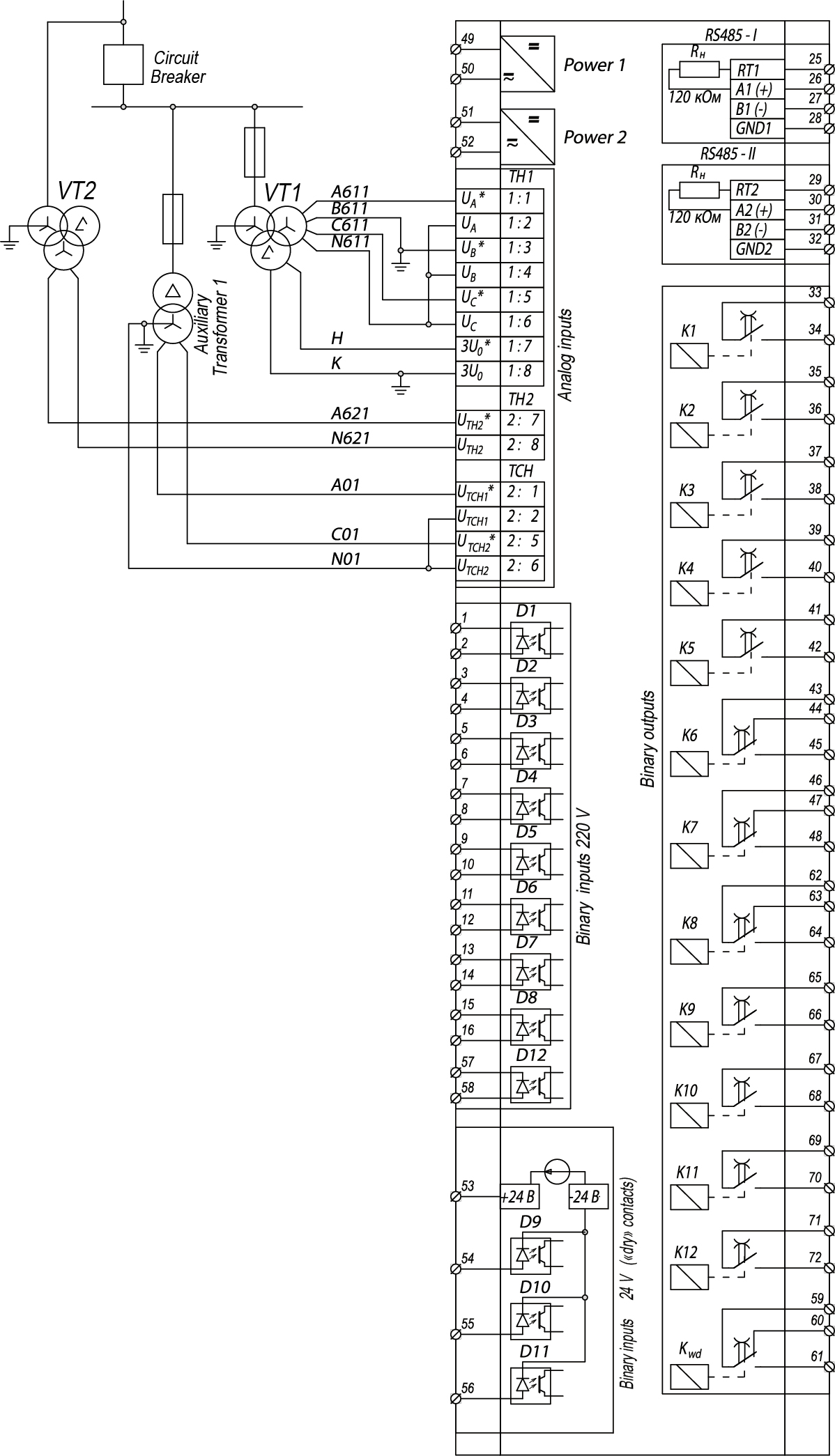
Wiring diagram of external circuits to the devices RZL-05.VT
![]() Download the catalog. Relay Protection and Automation Devices.
Download the catalog. Relay Protection and Automation Devices.
