Voltage indicator in networks up to 10 kV
IN-10-2

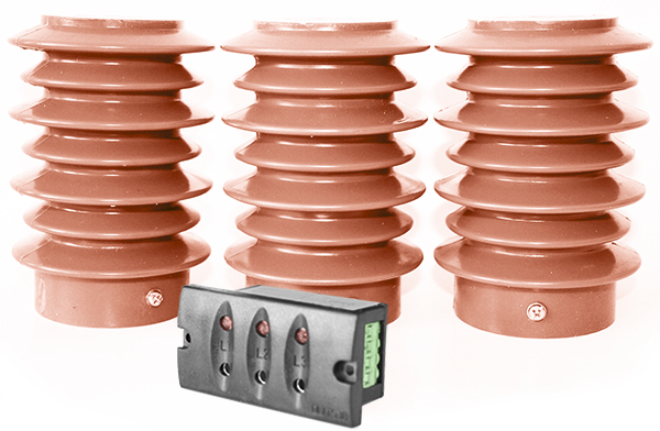
The IN-10-2 voltage indicator (hereinafter the indicator) is intended for visual monitoring of the presence of voltage in 10 kV switchgear and is used in a set with DE-10 capacitive sensors.
Terms of use
The indicator is intended for operation at temperatures from minus 40 to plus 60 °C, average daily air humidity of no more than 95% and is designed for installation in closed, explosion-proof and fire-proof rooms at an altitude of no more than 1000 m above sea level.
![]() Download the passport to the IN-10-2 indicator
Download the passport to the IN-10-2 indicator
Technical characteristics
| Parameters | IN-10-2 |
|---|---|
| Controlled voltage range | from 4 kV to 7 kV |
| Frequency of three-phase current | 50 Hz |
| The voltage at the input of the indicator (with a controlled voltage of 7 kV at the output of the DE-10 capacitance sensor |
from 80 to 110 V |
| The maximum voltage on the DE-10 capacitive sensor | 12 kV |
| DE-10 sensor capacity | 115 (±15) pF |
| The voltage of the electromagnetic blocking DC or AC (according to the order): |
24; 48; 110; 220 V |
| The maximum current of the relay contacts | 0,5 А |
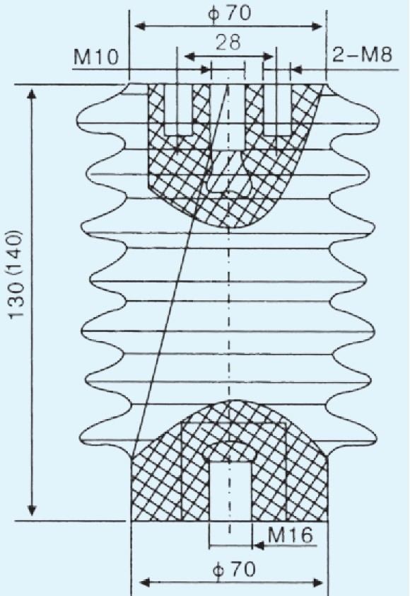
| Overall dimensions of the DE-10 capacitive sensor | no more than 140 x 90 mm |
| Weight of the DE-10 capacitive sensor | no more than 1.1 kg |
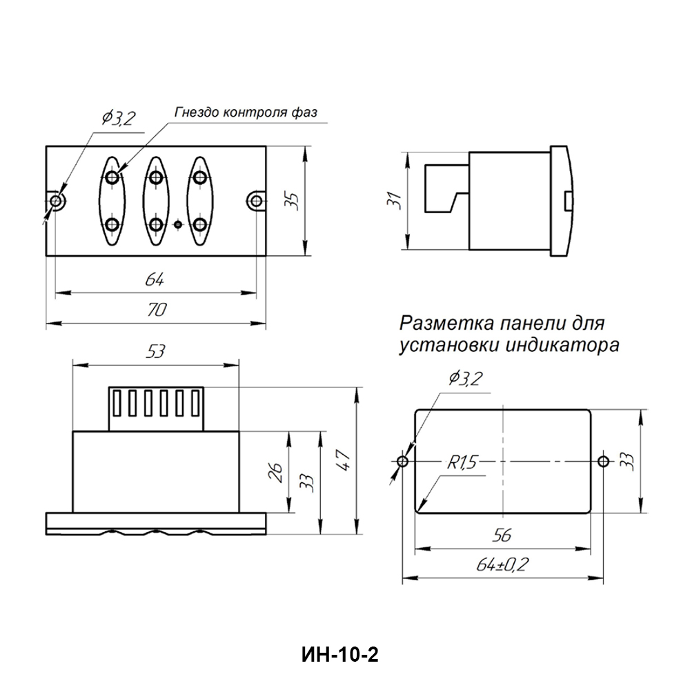
| Indicator weight | no more than 0.05 kg |

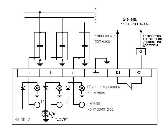
Fig. 1 – IN-10-2 connection scheme

Fig. 2 – Overall and installation dimensions of the DE-10 capacitive sensor

Fig. 3 – Overall and installation dimensions IN-10-2
Arrangement and working
Three-phase voltage control is carried out using an indicator to which three capacitive sensors are connected. A capacitive sensor is a polymer reference insulator with a built-in electrical capacitor. The sensor is attached to a metal platform inside the electrical installation, a voltage of 6 (10) kV is supplied to the upper part of the sensor. In the lower part of the sensor there is an output for connecting the voltage indicator.
The indicator is built as a three-channel voltage indicator, on the front panel of which three low-power light-emitting elements (LEDs) are installed, as well as an LED indicator that indicates the presence of voltage on any phase. The indicator also has a built-in electronic control relay with one contact group (contacts K1, K2), which can be used to block elements of high-voltage cells or telemechanics signals. If there is a voltage at the input of any of the capacitive sensors, from 4 to 7 kV, the relay contact is open (a mandatory condition is the presence of an additional power supply voltage on the relay according to the specified rating). If there is no voltage in all three phases, the relay contact closes.
Controlled three-phase voltage with a frequency of 50 Hz is applied to capacitive sensors, from the output of which the weakened signal is sent to the indicator. The maximum output current from capacitive sensors does not exceed 300 μA at an input voltage of 7 kV with a frequency of 50 Hz.
The indicator provides status:
- illumination of the LED of the corresponding phase when the voltage at the input of the capacitive sensor is from 4 to 7 kV;
- lack of illumination of the LED of the corresponding phase when the voltage at the input of the capacitive sensor is less than 1 kV;
- closed contact of the relay (K1, K2), in the presence of voltage at the input of any of the capacitive sensors from 4 to 7 kV;
- open contact of the relay (K1, K2), if the voltage at the input of all sensors is less than 1 kV.
WARNING! The measuring voltage on the sockets of the front panel of the indicator can reach values of more than 100 V.
