Three-circuit Time Relay
VL-81М

The VL-81M relay is a full analog of the VL-81 relay. This deviceis made on modern element base and has higher precision of counting of the time excerpts, wider range of the supply voltage and working temperatures.
The time relay has three independent circuits. In each of the circuits the required time setting can be set within one subband which is controlled by means of the switch on a front panel of the relay.
At the moment of giving supply voltage the counting time is reckoned in all three circuits. After the finishing of the time excerpt counting in any circuitan actuating of the appropriate output relay and ignition of the appropriate LED indicator (Figure 1) take place. Upon completion of the time excerpt counting in all three circuits the relay is in the waiting mode to the following cycle of shutdown / giving of supply voltage.

Features
- The wide range of the time of the relay actuation, 99-fold discrete control in one subband.
- The wide range of the supply voltages (two versions).
- Indication of the supply voltage presence (green LED indicator).
- Indication of the output relays condition (three red LED indicators).
- High precision of the time of the relay actuation in the range of working temperatures.
- High switching capacity of the contacts.
- Mounting on the plane or on the rail DIN-35.
- One change-over contact in the each circuit.
- The relay doesn't demand adjustment, fine tuning and other scheduled works.
Technical characteristics
- The range of the time excerpts (in one version):
0,1 s‑99 h with subbands (0,1‑9,9 s; 1‑99 s; 0,1‑9,9 min; 1‑99 min; 0,1‑9,9 min; 1‑99 min; 0,1‑9,9 h; 1‑99 h). - Additional error from the temperature changes - not more than 0,1 % for 1°С.
- Supplyvoltage, V (for the versions):
- DС/АС (90 – 264 V) direct, rectified and alternating current 50 Hz,
- DС/АС (18 - 100 V) direct, rectified and alternating current 50 Hz. - The range of working temperatures: from - 40 to + 55°С, relative air humidity makes up 93 % at the temperature 25°С.
- 5. The range of the switched voltages:
- direct current (DС): 12–250 V,
- alternating current (АС): 12–400 V. - Switching power:
- at the direct current for modes DС-11, W ... 30
- at the alternating current for mode АС-22, V•А ... 400 - Power consumption, V•А (W), not more than 5.

Additional technical characteristics
The relay is made in the unified modular enclosure for the projection mounting with the front screw connection of wires. The enclosure design provides the mounting of the relay on the DIN-rail 35 mm.
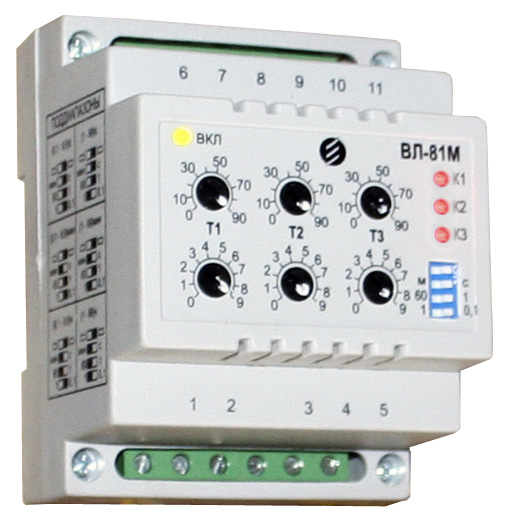
On the front panel there are decade switches for the settings control ( two for each circuit), microswitches of subbands and led indicators: one (green color) - for monitoring of the supply voltage presence, three (red color) – for monitoring of the output relays statuses.
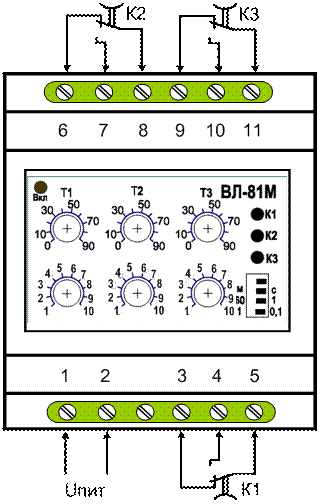
The appearance and the connection circuit of the relay are given in the Figure 2.
The level of the relay protection:
- by enclosure – IP30;
- terminal block – IP20.
Dimensions, not more than 70х90х65 mm.
Relay weight, not more than 0,5 kg.
