Intermediate Electromagnetic Relays
PE41, PE41‑М

PE41

in the transparent enclosure
PE41-М
Such a type of high-speed intermediate relays (DC/AC) has the actuating time not more than 0,011 s.
Application
The intermediate electromagnetic relays PE41 and PE41-M are intended for using in the protection circuits, control and automation of the electrical power equipment for the switching of the electric loads in the DC circuit with rated voltage 24V…230V and AC circuit with rated voltage 24V…400V (50 Hz and 60 Hz).
Working conditions
The range of the working temperature: -40 °С … +55 °С.
Shaking effect:
- in the range of the frequencies to 15 Hz with an acceleration of 3g;
- in the range of the frequencies to (15-100) Hz with an acceleration of 1g.
Technical characteristics
| Rated voltage of switched circuit, V:
direct current alternating current |
24 - 230 24 - 400 |
| Minimum current of contacts, A:
at a voltage of 24 V at a voltage of 110 V and more |
0,02 0,01 |
| Protection level:
relay screw terminal |
IР40 IР10 |
| Insulation test voltage, V:
among all electrically independent circuits, connected together, and relay enclosure among electrically independent circuits among open contacts of each contact sets between actuating and holding-upcoils |
2 500 2 500 550 550 |
| Isolation resistance of the dry and pure relay which wasn't in operation , МОм, not less:
relay in cold condition relay in warm condition |
20 6 |
| Mechanical durability, cycles, not less | 500 000 |
| Electrical endurance, cycles, not less | 100 000 |
Features
- The number of contacts makes up 6 groups in different combinations (make and break contacts);
- The actuating time of the high-speed PE41 relay for protection against ultra-high voltage makes up not more than 10 ms;
- The actuating limit of the relay is within 0,6-0,7 Urated (for DC) and 0,6-0,8 Urated (for AC); but release limit – not less 0,15 Urated (it counteracts the false actuating of the relay);
- The power consumption of the coils not more than 6 W (for DC voltage), not more than 10 VA (for AC voltage), that provides the possibility of the switching-in/switching-off of the relay by means of low-power contacts of the instrument relays;
- The switching capacity of the relay contacts allows to control by the coils of the switching-in/switching-off of the vacuum and oil switches;
- There is the possibility of the visual observation of a condition and movement of contacts without removal of the enclosure (there is a transparent cover in the location of contacts), and also in the version of using module via transparent enclosure;
- Relay construction provides the mounting by means of projection mounting on a vertical surface with the fastening by the screw or on DIN-rail with front/back wires connection (in the same version without additional details, studs, etc.). Working position in the space – any;
- Incombustibility and fire resisting property according to requirements for the devices which are not serviced during warranty period:
- enclosure: to 650 °С;
- terminal blocks and units holding current-carrying parts: to 960°С; - Taking into account the immunity to mechanical influences and main parameters, the relays are suitable for application on nuclear power plants
- Relay outputs allow to connect two wires with section 0,12-1,5 mm² (solder contact) and 0,75-2,5 mm² (screw terminal);
- Relay contacts: make contacts and break contacts;
- Connection circuits, outside dimensions, linkage dimensions, contacts combination (kind and quantity) of the relays PE41, PE41 М correspond and provide possible replacement relays RP17-1, RP17 4, RP17-5, RP221, RP222, RP225.


Outside dimensions

with front/back connection of the wires

and back conductors connection
Connection diagram

| Relays PE41, PE41-M | Direct current | Alternating current | ||||||||||
|---|---|---|---|---|---|---|---|---|---|---|---|---|
| Rated voltage, V | 24 | 48 | 110 | 220 | 12 | 24 | 36 | 100 | 110 | 127 | 230 (230) |
380 (400) |
| Coil resistance, Rа/Za, Оm | 45 | 150 | 850 | 3800 | 3,2 23 |
10,2 80 |
21 150 |
180 1340 |
200 1450 |
340 2270 |
850 6100 |
2700 20000 |
| Actuating/release of the relay | not more than 0,7 / / not less 0,2 Urated |
not more than 0,8 / not less 0,2 Urated | ||||||||||
| Power, W (VА) | not more than 6 | not more than (10) | ||||||||||
Convention structure of the type of the relay (PE40 – PE41) at the order

At the order of the relay it is necessary to indicate additionally: rated voltage (Urated) and rated current (Irated) of the coils (look at the table above), the way of the external wires connection (front/back), the way of the relay mounting (DIN-rail, screw terminal). At the order of the module (separate from the relay) it is necessary to indicate the voltage of the relay coils (look at the table above).

 Mounting on the DIN-rail |
 Additional module |
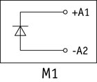
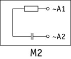
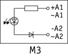
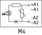
Schemes and characteristics of the modules
 |
 |
 |
 |
 |
| М1 - coil shunting, 24-220V DC, А1+, А2- |
М2 - RC element, 12-230V AC |
М3 - indication of the relay condition (red, LED indication), 100-230V AC, 110-220V DC, А1+, А2- |
М4 - protection from high-voltage surges and indication of the relay condition, (varistor and red LED indication), 12-230V AC, 24-220V DC, А1+, А2- |
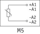
М5 - protection from high-voltage surges (varistor), 12-230V AC, 24-220V DC, А1+, А2- |
| Possible combinations of the modifications of the relays and modules | ||||
| PE41-20-ХХ-М1 | PE41-20-ХХ-М2 | PE41-20-ХХ-М3 | PE41-20-ХХ-М4 | PE41-20-ХХ-М5 |