Collecting Device of the Discrete Data
USDM-01

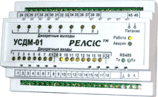
USDM-01 is the collecting device of the discrete dataand control with the data transmission under the MODBUS RTU Protocol.
The device is intended for the transmission of the discrete signals condition of the automation object to the monitoring (control) system and also for the implementation of the system commands via the built-in relays.
![]() Download the detailed description USDM-01
Download the detailed description USDM-01
![]() Download the software for USDM-01
Download the software for USDM-01
Device parameters
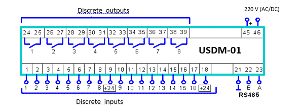
The number of the discrete inputs (DI), dry contact: 16.
The number of the output relays (OR): 8.
Maximum switching capacity of the OR contacts: AC:250V/5А; DC:30V/5А.
Time length of the OR closed contact: 100 ms.
Poll voltage DI (USDM-01 outputs): 24 V.
Supply voltage: 220 V (AC/DС).
Range of ambient temperature: -25…+55°С.
Mounting: DIN-rail 35 mm.
Dimensions: 140х90х63 mm.
Weight, not more than: 0,35 kg
Data transmission protocol
Protocol type: MODBUS RTU.
Reading functions of the DI condition: 2, 3, 4.
Function for the OR control: 5.
Function for the parameters recording: 6.
Range of admissible addresses: 1..255.
Broadcast instruction: it is absent.
Register addressing
| Address | Description | Range | Step | Format | Default |
|---|---|---|---|---|---|
| DI condition (data for reading only for functions 2, 3, 4) | |||||
| 0000 | DI condition | 0 - 65535 | 1 | D1 | 0 |
| Device configuration (data for reading (functions 3, 4) and recording (function 6)) | |||||
| 0001 | DI inversion | 0 - 65535 | 1 | D2 | 0 |
| 0002 | Device address | 1 - 255 | 1 | D3 | 1 |
| 0003 | Exchange rate | 1 - 16 | 1 | D4 | 3 |
| 0004 | Parity bit | 1 - 4 | 1 | D5 | 1 |
| 0005 | Data bit | 8 | 1 | D6 | 8 |
| 0006 | Stop bit | 1 - 4 | 1 | D7 | 1 |
| Remote control commands. Data for recording only (function 5) | |||||
| 0030 | Remote control/td> | D8 | |||
Data format
| Format | Discription | Format | Discription | Format | Discription |
|---|---|---|---|---|---|
| D1 | DI status
(0 – inactive, 1 – active) Bit 0 – DI1 Bit 1 – DI2 Bit 2 – DI3 Bit 3 – DI4 Bit 4 – DI5 Bit 5 – DI6 Bit 6 – DI7 Bit 7 – DI8 Bit 8 – DI9 Bit 9 – DI10 Bit 10 – DI11 Bit 11 – DI12 Bit 12 – DI13 Bit 13 – DI14 Bit 14 – DI15 Bit 15 – DI16 |
D3 | Device address. Integral number |
D7 | Stop bit
Bit 0 –1 Bit 1 – reserve Bit 2 – 2 Bits 3-15 – reserve |
| D4 | Bandwidth,
boud Bits 0-1 – reserve Bit 2 – 9600 Bit 3 – 19200 Bit 4 – 38400 Bitы 5-15 – reserve. |
D2 | DI inversion
(0 – not inverted, 1 – inverted) Bit 0 – DI1 Bit 1 – DI2 Bit 2 – DI3 Bit 3 – DI4 Bit 4 – DI5 Bit 5 – DI6 Bit 6 – DI7 Bit 7 – DI8 Bit 8 – DI9 Bit 9 – DI10 Bit 10 – DI11 Bit 11 – DI12 Bit 12 – DI13 Bit 13 – DI14 Bit 14 – DI15 Bit 15 – DI16 |
D5 | Parity bit
Bit 0 – NONE Bit 1 – ODD Bit 2 – EVEN Bits 3-15 – reserve |
D8 | Remote control
(1 – contact closure OR) Bit 0 – ВР1 Bit 1 – ВР2 Bit 2 – ВР3 Bit 3 – ВР4 Bit 4 – ВР5 Bit 5 – ВР6 Bit 6 – ВР7 Bit 7 – ВР8 Bits 8-15 – reserve |

![]() Download the detailed description USDM-01
Download the detailed description USDM-01
![]() Download the software for USDM-01
Download the software for USDM-01
